Adding objects to FlightGear

This evening I took my first (baby) steps into scenery design for FlightGear. Having done scenery design for Microsoft Flight Simulator for such a long time, it takes a little time to get used to the differences. Let me start with the good news, in the end I was able to see my objects. In this blog I will describe some of the things I came across.

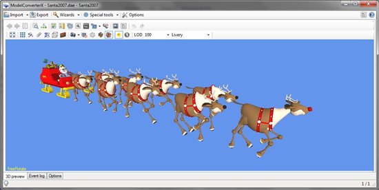
Getting the objects in a format that FlightGear can read was quite easy. I was using two models I had made before for FSX. So I just imported their MDL files into ModelConverterX, saved all textures as PNG and exported the model to the AC3D format. This only took me a few minutes to do.

Next I had to figure out how to place them in the scenery. In the end I succeeded, with help from the FlightGear Wiki, that has some interesting articles. Below are the things I liked and the things I didn’t like that much in the process.

Pros


  • The AC3D model files are just placed in a scenery or model folder, you don’t need to use another compiler to put them in some binary format.
  • The placement information is simply entered in a text file in the scenery folder, no need to compile to a binary format.

Cons

  • There is no slew mode, so I had quite some trouble to view my objects after placing. There is an UFO aircraft that has dynamics that come close to slewing, but I still find it hard to control.
  • When placing the object you need to enter the altitude above MSL. So for one object it took a bit of trial and error to get this right. An option to just place them at terrain altitude would be useful.
  • I could not find a way to place my objects in their own scenery package, the placement information goes into the same tiles as the global scenery. With just a few objects this is not too bad, but I can imagine it because a mess if you have to install a lot of scenery (on the other hand, it seems almost all scenery comes with the global package, so maybe it is not such a big issue).
  • The placement information needs to go into tile files with a very specific filename. I had to go into FlightGear to find the name for the location of my object, I would find it easier if you could just specify a position of an object. Maybe there are some tools that assist with this, I still have to look at that.
  • I couldn’t find a way to start FlightGear at a specific latitude and longitude, it seems you can only start at an airport.

It was a nice experience to add some objects tonight, I am sure I will be exploring FlightGear development more. Maybe not to make full addons for it, but it is interesting to see how the development processes for different simulators are.

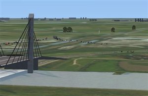
On the other hand there is enough room for improvement of the FlightGear scenery, the default scenery reminds me of how FS looked when I started to make scenery. For example, I placed an watertower near Hoogeveen in the Netherlands and the airfield there was represented with an asphalt runway, while in real life it is just a grass runway. And the landclass terrain scenery is also not so accurate. The second church I placed it supposed to be in the city centre, not in some green fields.


Coordinate confusion – part 2

After all the theory I blogged about yesterday, I thought it might be a good idea to illustrate the difference today. So let’s take a quite common example. I have taken the threshold coordinates of runway 06-24 from Amsterdam Airport Schiphol. And I have chosen the reference point to be near the middle of the runway. What are my XY coordinates of the threshold when I am modelling the runway in my 3D editor?

The two screenshots above show the XY coordinates for the threshold of 06 (top picture) and 24 (bottom picture). In the screenshots you can see both the flat earth coordinates (as used by FS2004) and geocentric coordinates (as used by FSX). Let’s ignore the Z component of the geocentric coordinates for now, although that shows that at the distance of this runway (1.5 kilometre for the reference point on each side) the elevation difference due to the curve is about 20 centimetres already.

But what do the other coordinates tell us? You can see there is around 1 to 2 meter difference in the values in both X and Y direction. And the geocentric coordinates have a bigger values than the flat earth ones. So that means that if something is modelled in the FS2004 coordinates, that it will appear slightly smaller in the FSX world. That’s why ground polygons with different reference points that fit exactly in FS2004, will  have some gaps between them in FSX.

The little converter that I show the screenshots from will be part of the next development release of ModelConverterX by the way, you can find it in the Special Tools menu.

Coordinate confusion

OK, I got a question for you. What kind of coordinates does your 3D modelling tool use? I mean a tool like GMax, FSDS, SketchUp or 3DS Max. Ah, that is an easy question you must think now, all of these programs use a 3D axis system where you model your object in meters (or maybe feet or inches for the developers in the US). So that question does not seem so difficult, does it?

But how do these meters related to the position of the object on earth? The earth is a sphere (or more accurate an ellipsoid) and the location of an object on the earth is usually defined with a latitude and longitude. In this blog post I want to discuss how this relates with the XYZ coordinates you use in your modelling tool.

Why should you know more about this? If you are just making a model of your house or other small objects it is probably not so important. But if you are also making big objects or runways in your 3D modelling tool it is important to know that things end up in the world where they are supposed to be.

So how do those XYZ coordinates translate to a position on the earth? The XYZ coordinates are flat, so it is basically a question on how to present a sphere in 2D. Quite similar to the challenges you face while drawing a map of the earth. And if you look at different world maps you might notice that they do not all represent the world in the same way. Look for example at Greenland, it is often represented in different ways. The image above shows three of these. It depends on the projection or coordinate system you are using. So to know how our XYZ coordinates translate to a location on earth we need to know what kind of coordinate system FS is using.

FS2004 represents the area around you as a flat world and there formula’s to convert between latitude/longitude and XY are well know. This is usually called a local flat earth projection. But you should still be careful, because there are small variations to these formula’s that are also called flat earth. Using these formula’s you can make sure that the runway you draw in your 3D modelling program ends up exactly at the threshold coordinates from your AIP for example.

For FSX things are slightly different, since the world around you is no longer rendered as flat. Instead it is represented as a curved surface, which is it in real world as well of course. This also means that the formula’s that worked for FS2004 are no longer valid in FSX. To convert between XYZ coordinates and latitude/longitude you need to use so called geocentric coordinates. Geocentric coordinates are basic XYZ coordinates where the origin is the centre of the world. However for 3D objects they are expressed relative to the reference point of that object.

So what does this mean for me, you are probably thinking by now? As you had probably expected already these two coordinate systems do not line up exactly with each other. So imagine you have made a 3 kilometre long runway for FS2004. In the FS2004 (flat earth) world it is placed perfectly. But if you load it in FSX you will see that the thresholds do not end up at the same latitude and longitude anymore. The difference won’t be very big, but with such a long runway it can easily be a few meters off. So that means that runways and aprons made for FS2004 will not be positioned at exactly the same location in FSX. For smaller buildings there will be an offset as well, but in those cases the offset is usually no more than a few centrimetres and you won’t really notice it.

And to make things even worse, it seems there is an inconsistency in FSX that renders attached effects using the flat earth coordinates, while the geometry of the object is rendered with geocentric coordinates. This means that the further away from the origin you go, the most these two element will offset from each other (while in your 3D modelling tool they are at the same lcoation).

OK, I guess by now you will understand what is happening. But how can you solve this? I think if you are creating big features like a runway it is a good idea to be aware of what is going on. And when you use a background image in your 3D modelling tool you should spend some time to make sure it is aligned correctly. For FS2004 you would need to make it flat earth projection and for FSX geocentric projection. How to do this is unfortunately not so easy, so I guess I would have to discuss that in another blog post later on.

For now I hope you are more aware of some of the things going on inside the rendering engine of FS and how that influences the scenery you are making. Especially if you try to make things very accurate.

AC3D support in ModelConverterX

I have added support for a new format to ModelConverterX today, this new format is the AC3D format. It is commonly used by FlightGear for aircraft and scenery models. In the next development release you will find a reader and writer for the AC3D format. There are a number of limitations at the moment:

  • Shaded objects are not being read or written correctly. This is because the format does not directly store the normals of the polygons, but only if it is smooth shaded or not. I am still figure out how to interpret this correctly in ModelConverterX.
  • Only geometry is read or written, so no animations at this moment. I think FlightGear uses an extra XML file to specify animations, I will have a look at this later.
  • When exporting to AC3D I think the axes system used is wrong for FlightGear, so it could be the object is on its side if you import it now. I am still checking this.

Besides that I must say that I tested it with a number of FlightGear models, but I am sure that there are models that have different features and will not work directly. Please let me know if you have trouble, so that I can improve the tool.

I also haven’t tested the AC3D output in FlightGear itself, but OpenSceneGraph can visualize it. I guess I should head off and install FlightGear…

Effects with an offset

A topic that has been raised frequently on the FSDeveloper forums recently is that effects attached to an object in FSX have an offset in their placement. Especially when you use these effects for your taxiway lighting or approach lights that is an annoying “feature”.

So tonight I did a little experiment to see if I could reproduce these complaints. I placed three objects at 250 meter distance, each with an effect at the top. The last one was 500 meters from the reference point and as you can see the effect is not at the top of the object, but has an offset. At 500 meters from the reference point this offset was about 0.7 meter already.

Next I compared this offset with the difference you get when using the curved earth or the flat earth coordinates. And that difference was exactly 0.7 meters as well. So it seems the attached effects get corrected for the curved earth, while the geometry does not. That’s what gives the offset.

So know that the cause is known, it should not be too hard to fix this. I think I will add an option to ModelConverterX to correct the position of attached objects. But if you have a better idea how to fit this correction in your modelling workflow let me know.

Oops a mistake, undo please!

It’s probably on of the key combinations most used in computer programs, Ctrl-Z, to undo your last action. Until now ModelConverterX did not have any undo functionality. When I started with the tool an undo function was not really needed, since it was an object converter. You loaded an object and exported it into another format. If something went wrong you could just load the same object again.

But over time more functionality has been added to ModelConverterX and now it is not uncommon to perform a number of actions on the object before exporting it again. For example change some material attributes, add an LOD or reduce the amount of drawcalls. With all of these actions it can happen that you make a mistake of course. So I have now added an undo function to ModelConverterX as well.

The undo function works as in most programs. It allows you to undo the last changes you made. Either by pressing the undo button at the toolbar or with the common Ctrl-Z shortcut. ModelConverterX has no limit to the amount of undo’s you can perform at the moment, although the amount of available memory will put some constraint on it. In the options you can disable the undo functionality at all if you are running out of memory. Please let me know if limiting the amount of undo’s is necessary, but from my test I expect that the memory usage is OK.

Besides undo, there is also a redo function, which will undo your last undo. This works with the common shortcut Ctrl-Y or the button at the toolbar. In ModelConverterX the keyboard shortcuts Ctrl-Z and Ctrl-X were used before to select the previous and next object. Since that conflicts with the undo key, I have changed those two to Ctrl-X and Ctrl-C now.

Performance indicator render mode

I have added a new experimental render mode to ModelConverterX. This mode gives the object a colour based on the amount of texture vertices at a certain location. So this mode should help you to see where your object can be optimized further to increase performance. I have made a quick video to demonstrate it, since this is tricky to explain in words:

When analyzing the result keep in mind that this is calculated per modelpart. So where two different parts, with different material, meet, you will not see a higher texture vertex count. That is by design. As I already mentioned in the video, this is an experimental mode. I hope it helps to understand performance better, but please let me know if you have suggestions on how to make it more useful.

The return of DrawCallMonitor!

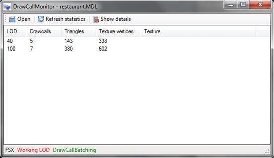
In my previous post I already mentioned that the object statistics shown in the DrawCallMonitor tool and in the Object Information form of ModelConverterX differ. I have done some more studying on this and it is hard to say which one is better.

DrawCallMonitor gives the right statistics if you want to know how many triangles, drawcalls and texture vertices a specific MDL file has. ModelConverterX on the other hand gives a good indication of how many drawcalls, triangles and texture vertices you will get when you export the object from that tool. There can be quite a difference between the two tools. I think this is due to different strategies, ModelConverterX tries to export objects with as little texture vertices as possible. Many of the default MDL files can be optimized to use less texture vertices, but I think at the moment they are build so that the triangles can be drawn with continuous triangle strips. It would be an interesting topic to compare those two approach performance wise. But that is a subject for later.

Anyway, having said the above, it is clear that a tool like DrawCallMonitor is still very useful when trying to examine MDL files. So I have decided to put the tool in the ModelConverterX development release. From tomorrow that release always contains the latest versions of ModelConverterX, FXEditor and DrawCallMonitor. The version of DrawCallMonitor is almost the same as the one released on the forum before. I have only made a few small user interface improvements. But now you are sure to have the latest version in a convenient place. So welcome back this tool to your tool suite.