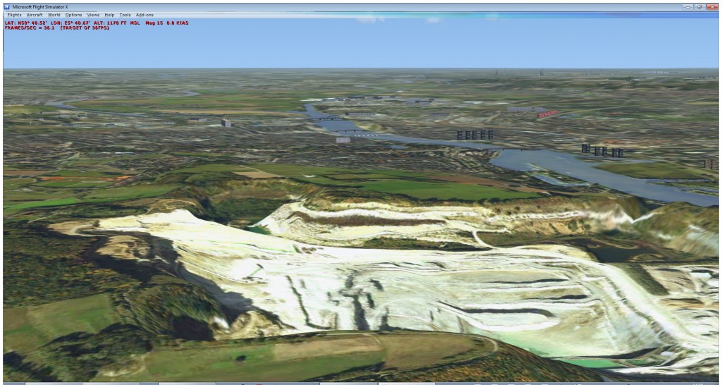
This week I did some work on creating elevation data for our Dutch NL2000 scenery. I would like to share the challenges and solutions I encountered.
For the NL2000 scenery we have been looking for replacement elevation data for quite a while already. The default FSX elevation data is OK, but it is not really detailed. Although the Netherlands is not mountainous, it would be nice to see more detail in the hills and dunes.
Our first challenge was to find source elevation data that we could use. Given that it is a freeware project we we looking for free or contributed data sources. Just this week I found at that the Dutch government has made 25 meter resolution elevation data available for free. So this sounded like good news. However an examining the data a bit more, it turned out that certain parts of the data were not filtered. This means that the data does not only contain the terrain there, but also elevation points that belong to buildings and other structures. When I tried this elevation data in FSX, especially the cities turned out to have a lot of noise in the data.
So this did not look good. But fortunately a vector file was provided that contained the areas were the data had not been filtered. So using this vector data it should be possible to replace the elevation data in those areas with another source. But where to find another source?
In the end I decided to use the vector data set of the Netherlands that the government has also made available. This vector data set does contain contour lines and elevation points. So how to turn this data into raster data so I could merge it with the other set?
In the end it turned out that with GDAL this was not so hard to do. Using gdal_rasterize I could make a raster burning in the elevation data of the contour lines and elevation points. And with gdal_fillnodata I could fill the parts in between. Here are the scripts I used:
gdal_rasterize -a hoogte -a_nodata -32768 -ts 10000 10000 IsoHoogte.shp test.tif
gdal_rasterize -a hoogte HoogteOfDieptePunt.shp test.tif
gdalwarp -t_srs "+proj=latlong +datum=WGS84" -srcnodata -32768 -dstnodata -32768 test.tif test_wgs84.tif
gdal_fillnodata test_wgs84.tif test_wgs84_fill.tif
The results of gdal_fillnodata are not perfect, sometimes you can see some artifacts in the elevation data. But since I mainly wanted to use this data to replace elevation data in cities, it was not a big issue. Most cities in the Netherlands are relatively flat.
So how did I merge the two? With GDAL again. First I burned a big negetive value into the elevation data based on the vectors of the cities. And then I replaced those parts with the other dataset. Here is the script again:
gdal_rasterize -b 1 -burn -1000000 stadspolygonen.shp ahn_stad.tif
gdal_calc -A ahn_stad_wgs84.tif -B ..\top10\test_wgs84_fill.tif --outfile ahn_merge.tif --calc '(A==-1000000.0)*B + (A!=-1000000.0)*A'
The final GeoTIFF could be put in FSX very easily with resample. So that resulted in nicer elevation data for the Netherlands. As NL2000 team we are still testing the new data, but it might end up in a future update of the scenery.


 A second option is to find and use some vector data that contains information about population density, amount of houses in an area or something similar. For the Netherlands I found some (free) data from the national statistics bureau that gives information about amount of people, population density and even amount of houses for the entire country. This information is given for cells of 500×500 meter. To the right is a screenshot of this data.
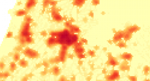
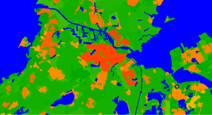 A third option would be to use a raster image with population density data. I did not yet find a good source for this however. I found some population density data at the EEA website that covers most of Europe. But it only showed the population density per municipality. Which means that the city centre and the suburbs have the same density. While the aim is to vary the autogen between those parts of town of course. I have included a screenshot of this data on the right again. But there might be better data available and then using raster data would be a good idea.
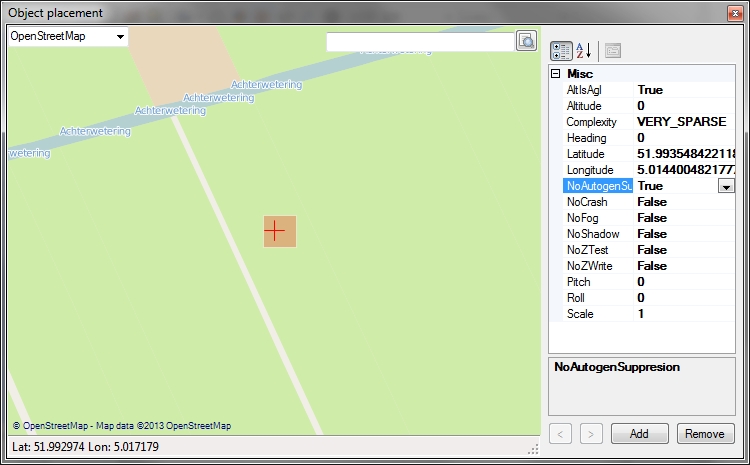
 I have added support for another file format to scenProc, it is now also possible to read KML files. This means that you can now use Google Earth as well to draw your points, lines and polygons. And then use scenProc to convert this data into autogen for FSX.