Match texture function fixed

I have just fixed the match texture function in the material editor. Since the new material editor was introduced this function was broken, but it is working again. With this function you can look for the same texture, with a different name in the specified texture folder.

I hope to finalize the new material editor in the next couple of days. So that means I want to finish the drawcall minimizer improvements and do some more robustness checks for the material editor in general.

Another nice feature I introduced today is a function that can replace a material with double sided property set by additional triangles. This means a separate triangle is made for both sides. Sometimes it can be more efficient to have a few more triangles if that means you can reduce the amount of drawcalls.

Merge objects

I have added a new function to ModelConverterX, you can now merge objects. After you bring up the form there are a couple of things you can do:

  • You can specify the LOD that should be used for the model you are importing. So this allows you to import another model as a lower level of detail. Or if you give the same LOD as your current object they will be combined.
  • You can specify an offset compared to the current model, so that you can put object besides each other.
  • With the load object button you can load another object from file to be inserted.
  • Alternatively you can also use the list of objects given. This list will show all other objects that are currently loaded into ModelConverterX. So for example if you have loaded a library, all the other models will be shown.

Once you have set all options the way you want, you can press merge to start the merging of the objects.

A new blogging home

For those of you who have been following me at my blog at msmvps.com, welcome to the new location of my blog. From now on you will find my posts about scenery design, tools and other things that interest me here.

As you can see all old posts have already been migrated. So I hope you will feel at home again here.

Specular and fresnel effects in preview

The next development release of ModelConverterX contains improvements to the rendering of the object in the preview. The two biggest changes are that the specular hotspot and the fresnel effects are now shown in the preview as well. I am not convinced that the fresnel effect is exactly like in FSX, but I think it is rather close at the moment. Besides those two changes there are other smaller improvements as well, for example reflections work more like FSX now and also some additional material settings now have an effect in the preview.

Classify building footprints

I have been adding more built-in attributes to scenProc recently, to allow you to classify buidling footprints in different types. Then for each type you can make different kind of autogen. This work is not yet finished, but in this blog post I want to show what you can do already now.

Please read the scenProc manual to see which attributes are available and what they mean. Below is a scenProc configuration file I used to create autogen around the city of Amsterdam:

# Amsterdam autogen test
IMPORTSHP|buildings_adam.shp|NOREPROJ
#
ADDATTRIBUTE|*|BUILDCAT|5|1
ADDATTRIBUTE|FCONVEX=1|BUILDCAT|4|1
ADDATTRIBUTE|FNUMPERPANG>3;FNUMNOTPAR<2;FNUMVERT<10|BUILDCAT|3|1
ADDATTRIBUTE|FAREARAT>0.85|BUILDCAT|2|1
ADDATTRIBUTE|FNUMVERT=4;FNUMPERPANG=4|BUILDCAT|1|1
#
EXPORTSHP|*|bla
#
SPLITGRID|AGN
#
SETAGNBUILDINGHEIGHT|1.0;0.4;0.2;0.0
CREATEAGNGENBUILD|BUILDCAT<2;FWIDTH<20|{5ae04eb6-934c-4f63-bb48-5e7dee601212}|MAXRATIO=2
CREATEAGNGENBUILD|BUILDCAT<2;FWIDTH>20|{6089A0BD-CED1-4c47-9A9E-64CDD0E16983}
#
WRITEAGNFILES|c:flightsimnl2000nl2k_v4_resample_NHtexture

Let me explain what is done here. First I import the shapefiles that I want to use. Next I use the (new) ADDATTRIBUTE step to calculate some new custom attribute. This is where most of the work to classify the buildings happens. I have defined the following categories for my buildings:
  1. Rectangular
  2. Nearly rectangular
  3. Can be represented by a number of rectangles
  4. Convex polygons
  5. Concave polygons

So first I set all features to category 5. Then with the second ADDATTRIBUTE step is make sure all convex buildings are category 4. The FCONVEX attribute is used for this. All buildings that have at least 4 perpendicular corners and no more than 2 edges that don’t have another parallel edge and have less than 10 vertices are step to category 3. All buildings where the difference between the footprint area and the bounding box area less than 15% are set to category 2. And finally all footprints with 4 perpendicular corners are defined as rectangle (category 1).

Now I use can this new attribute BUILDCAT to create the autogen buidlings. I use category 1 and 2 for the rectangular autogen. The other three categories are not used in this example. But my plan is to add another step that can split the footprints of category 3 into a couple of rectangles to represent the shape. For category 4 and 5 maybe the polygonal autogen can be used or else I think it would be a good idea to create MDL objects from those footprints.

Of course the classification I show now is not how it should be done, you are free to define your own rules in the ADDATTRIBUTE steps. Let me know if more attributes are needed for that.

Below is a screenshot that shows which footprints are classified in which category for part of the city. As you can see it is not perfect yet, so I will continue to do some more testing to refine my rules. Once I found a set that works well, I’ll post an update of course. Especially for category 3 the results as not as good as I hoped, so I will try to find a better algorithm there.


Built-in help

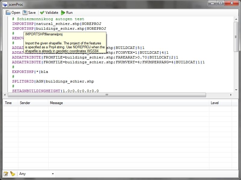
In the last two days I have made scenProc a little more robust. Before any mistake in the configuration file would usually result in a crash of the entire tool. That has been changed now. The tool will now check if you provided the right amount of parameters and give a warning when that is not the case. Sometimes it will also check if the parameters provided are of the right type, but that is not yet supported for all available processing steps.

Another change I have made is that the tool now has built-in help. If you enter scenproc –help in your command prompt you will get a list of available processing steps. If you type scenproc –help stepname you will get additional information about the processing step with the given name. This includes information about the expected parameters and what the step does.

I hope these two changes make the tool a little bit easier to use for you. Oh, and one more thing. You might see there are more processing steps available than documented on the wiki. Those other steps are used to make ground polygons from dxf or shp files. But they are still under development and might be a bit buggy, so I would not advice you to use them on a serious project at this moment.

Some autogen thoughts

I am going to spend some time on the scenProc tool again the coming weeks. It’s time to finish some of the features of that tool and make it even easier to make autogen. But of course there are some challenges left.

One of the main challenges is that most FSX autogen must be rectangular. So for a group of houses as shown above that will work. It is not so hard to define a rectangle for each of them. Some have a small extension, but even if you ignore those the result will look quite good. For the buildings shown below it becomes a little harder already, but you could represent their shape with 3 rectangles that partly overlap. An algorithm can be defined to derive those rectangles.

So, so far it seems quite possible. But now look at the buildings below.These are all very irregular shaped. If you would try to represent these with rectangles you would always get parts sticking out or parts missing. Not really a good approach thus.

You might be thinking, right, that’s why we have polygonal autogen buildings in FSX as well. But unfortunately the polygonal autogen buildings must have an internal courtyard. This makes them very hard to use for this kind of shapes. I really wish Microsoft would have made them without the courtyards as well. But it seems that is not possible.

So my challenge is to find out how to classify the building footprints from the vector data. Which footprints can be represented by normal autogen buildings, which ones can be represented by row houses or by polygonal autogen. And which footprints can better not be represented by autogen at all.

For that last category it might be an option to create them as normal MDL scenery object. From the footprint it is possible to create a building directly. And by using drawcall batching it might not even be that hard on the performance. That’s something I would like to test as well.

And finally I think I will try to analyze the autogen format of the polygonal buildings a bit more. Maybe, maybe, there is some undocumented bit to remove those courtyards? Let’s keep dreaming….

All map images are from OpenStreetMap.


User interface change

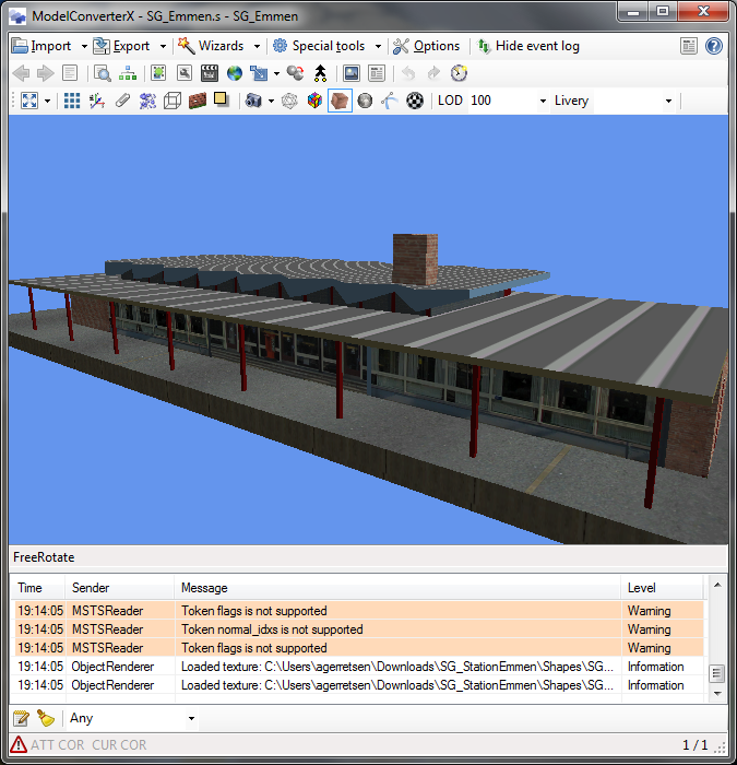
I have changed the main user interface of ModelConverterX a bit, actually it has gone back to some of the concepts that the tool used in 2008 already. I did remove the tabs that were used for the preview, event log and options. Instead of those tabs the options are now on a separate form, which can be opened with the Options button at the top toolbar. The preview and the event log are both shown at the main screen. There is a splitter in between, so you can change the size of the preview and event log as you wish. There is also a button to collapse the event log completely, if you want to maximize the preview. Below is a screenshot of the new user interface.

Why did I change this? Because I think it would be better to have the event log visible while you are working with your object. That way I think it is less likely that users miss an error or warning in the event log.

Problem reporting

user: He, your tool does not work.

me: What do you mean? What are you trying to do and what goes wrong?

user: When I import my object it crashes. You need to help me, I have to convert this object.

me: What is the error message you get at the crash? Can you maybe send me the object to debug?

user: Never mind, I fixed it already.

OK, this is expurgated a little bit, but this is how a typical user interaction about a bug in one of my tools might go. Both for the user and for me it is not an easy process. So I have made some to ModelConverterX now to make the progress of reporting bugs easier.

Every time you have a crash in ModelConverterX you will see the error handler screen as shown on the right. To help me fix bugs in the tool, I would like to ask that you send in the error everytime you have a crash (of course only once for the same crash).

But what happens when you send in the error? The tool will then automatically make an entry in my bug tracking system. In that entry it contains the error message and the stack trace that helps me to find what was going on. If you select the checkbox to upload the file that is causing the error, also the object you were trying to load will be attached to the bug report. If possible, please send the object as well, since that helps me a lot with debugging. And that’s all. No other information is being send about you or your computer.

So please use this function if you encounter crashes in the future. It will help me to improve the tool and it will help you to get a tool with less bugs quicker.

Correcting for the FSX curved earth

One of the main differences between FS2004 and FSX when it comes to rendering the earth, is that FS2004 assumes that the earth is locally flat while rendering the scene, while FSX uses the correct curvature of the earth as well. But this has some consequences for scenery designers. When you make ground polygons they are usually flat in the design tool, but putting them on the curve of the earth will mean that the ends will float in the sky. The ground polygon wizard of ModelConverterX does correct for this problem, by shaping your ground polygons to follow the curve of the earth.

But this problem not only affects ground polygons, also normal buildings or animated vehicles can have this problem. Therefore an experimental function to correct for this problem was in ModelConverterX for a while already. Over the last week this function has been expanded and improved and therefore it now has become a new editor: the Earth Curve Editor. You can load this editor by clicking on the icon with the picture of the round earth.

From this editor you can set the position of your object and choose what you want to correct. Entering the exactly altitude of the ground is very important to get the correct correction.

A problem in FSX noticed before is that attached effects are offset from the geometry, the further you get from the reference point. This is related to the curve of the earth as well. So there are two chooses for a correction:

  1. You correct the geometry to follow the curve. This will also correct the path of the animations and attached platforms. Attached objects, like effects, are not corrected however. Once the geometry has been corrected they line up again.
  2. You only correct attached objects, like effects. This correction will move them to line up with your geometry. But if your geometry is big, it will still float at the end. So in general it is probably better to use option 1 instead of this one.

This new editor is in the latest development release. I hope it proves to be useful and let me know if there is any feedback.