As you have probably noticed I haven’t been active at all recently with my tools or on FSDeveloper. I already reported before that we bought a house and are busy renovating it. But on top of that our second son was born 3 months too early. So that means that at the moment we step any spare time we have in the hospital to visit him. Logically the FS hobby is on hold for a while now. Luckily our son is doing OK, he’s still very small, but growing. The expectation is that he has to stay in hospital for another 2 months probably. So hopefully next year I can spend some time on the FS hobby again.
Busy
As you might have noticed already from the lack of activity on this blog and the fewer updates to my tools, I’m a bit busy at the moment. We have just bought a house and next week we finally get the keys. But the house also needs some modernization before we can move in, so in the last few weeks I have already been busy planning for that.
I guess this lack of time for FS will stay until we have moved into the house. So until then expect less updates of the tools and sometimes I might also reply slower in the FSDeveloper forum. Although it is mainly the programming that suffers, since I can still check the forum from my phone, but I can’t code on ModelConverterX or scenProc that way.
Nantucket Series: Part 1 – Creating buildings
Here is the first part of the series of tutorials I announced a couple of days ago about creating autogen for the island of Nantucket with scenProc.
The Nantucket tutorials
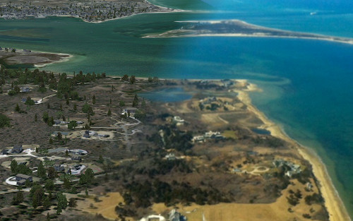
Over the last I have been using the island of Nantucket (Massachusetts) as a sandbox to try all kind of autogen techniques and to develop new features of scenProc. Coincidentally Bill Womack is working on a scenery of Nantucket airport as well. So my test autogen project will even end up in a real product. And with the help of Bills artistic skill the autogen textures also got much more realistic than I ever could have done.
Now that the autogen project is nearing its end and scenProc is also nearing the release of a stable version 1.0, I thought it would be a good idea to make some video tutorials about the things I have learned during this project. So with this blog post I want to announce a small series of video tutorials that will cover the different aspects of this project. I plan to give you one or two tutorials every week.
At the moment I have the following “episodes” planned, but as usual things can always change as I go along.
- Creating the buildings (finding the data, how to prepare it for creating FS autogen buildings)
- Customizing the buildings (adding custom textures and roofs)
- Creating the vegetation (finding the data, how to create the autogen)
- Customizing the vegetation (using custom vegetation models for even more realism)
- Creating the library objects (electricity poles, gas stations)
- How to merge all these custom autogen configurations when installing a scenery
Let me know if there are other topics you would like to see covered!
P3D v2 and GPW gaps
In my post from two days ago I reported about gaps in my ground polygons, this lead me to discover the different resolution of BGLComp and BGLC generated BGL files. But it turned out that the gap was also caused by a programming mistake I made. The round earth correction was not completely correct for the P3D v2 output. I have fixed that now and as a result you can use the option to divide the polygons in a grid again. For the FS2002 style polygons that gave a better performance, I guess we need more testing to see if that is also the case for P3D. But in general it should be more efficient for the rendering engine if not all polygons have to be drawn.
The observations about the different positional resolution still stand, but they were not the cause of my gaps. So gaps fixed and still something interesting learned.
GPW update for P3D v2
I have just put an update of the ground polygon wizard (GPW) in the development release of ModelConverterX. With this update it is now possible to export P3D v2 MDL files from the GPW as well. These can be used in P3D v2 and it allows you to use the full material properties on your ground polygons. As Lockheed Martin has announced this is the way forward, the old FS2002-style ground polygons will be removed in the next major release.
Are there limitations in the P3D v2 export? Yes there are:
- Seasons are disabled in the wizard, as these can’t be combined with MDL files
- The visibility range is disabled in the wizard, as MDL files work with LODs. For the moment only one LOD is exported.
- It is no longer possible to split your complex ground polygons into multiple groups. For P3D v2 they are always exported to one MDL file. This is because the BGLComp placement is less accurate and with multiple groups you would get gaps in between. If this leads to performance issues I can see if there are other optimizations that can be done.
- I did notice with my test objects that some of them seem to disappear or flicker a bit in the distance (10 nm away or so). I guess when combined with some resample photo scenery below you will hardly see this. But maybe this can be prevented by adding LODs or something else. That’s something that needs some more testing, let me know if you have any issues or ideas on this.
I would suggest that you don’t use this new feature for production work yet. I do expect there might be a few bugs here and there left. So please go ahead and try to break test this new feature. Let me know if you have any suggestions or issues.
GPW and P3D v2
Today I have been experimenting with updating the ground polygon wizard of ModelConverterX to also export P3D v2 MDL files for ground polygons. Given the recent announcement by Lockheed Martin that the FS2002 style polygons will be dropped in the future, it became time to update the GPW.
The good news is that it was quite easy for me to ouput the ground polygons as P3D v2 MDL files. The layering information is stored in the material zbias property now, but for the rest it works similar to the FS2002 style polygons approach.
But I also found a problem. It seems the positional accuracy of BGLComp compiled scenery is much lower than that of SCASM based scenery. As a result of that, gaps will appear between the polygons when they are split up in different groups. I usually do this in the GPW to increase performance. So in the old FS2002 style code there would be multiple reference points, each containing the the polygons closest to that point.
I need to do a bit more thinking on how to handle this. Either I will drop the option to group polygons for P3D v2 output or I need somehow use the same reference point for all groups. So there is some more experimenting to do before I can finish the GPW update.

And for those of your interested in the math of the positional accuracy. In the BGLComp BGL format the latitude and longitude are stored as 32 bit integer values. This means that an increase of the lat/lon value by 1 corresponds to 3.3528e-7 degrees for latitude and 4.4703e-7 degrees for longitude (at the equator). That roughly corresponds to 4 to 5 centimetre accuracy.
In the old FS2002 style scenery the latitude and longitude are stored as a 32 bit integer plus a 16 bit integer. This means that an increase of the 1 corresponds to 1.3731e-10 deg degrees for latitude and 1.2790e-12 degrees for longitude (again at the equator). This corresponds to an accuracy of around 0.015 millimetre.
I never realised before that the accuracy of placing objects was so different between both methods. The accuracy of the old method is probably a bit over the top, as you won’t see that difference. But for the BGLComp approach I would have expected a little more accuracy actually.
Updated options and better P3D support
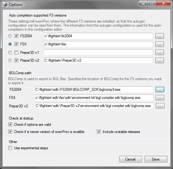
I have updated the options form of scenProc and also added better P3D support. Before you had to trick the tool by pointing the FSX settings to P3D. You can see a screenshot of the new form below.
At the top part of the form you can choose which FS version is supported for the auto completion. So you choose from FS2004, FSX, Prepar3D v1 and Prepar3D v2. scenProc will then read the autogen configuration files from the selected version. You can enable only the versions you are developing for. The enabled versions here don’t influence to which FS version you can export, it’s only for the auto completion in the scenProc GUI. The radio button at the wrong is used to select the preferred version that will be selected by default.
Below you can set the paths to the different versions of the BGLComp compiler. This compiler is used by the EXPORTBGL step. If you don’t export to BGL, you don’t have the set these paths.
At the bottom of the form there are a few other options that influence the behaviour of scenProc. Set them as desired.
RADItor update
I have made a small update for RADItor. When you drop a file on the EXE, shortcut or on the main form it will now automatically be loaded. So you don’t have to manually browse for the file anymore in that situation.
The new version can be downloaded from the RADItor page.
Batch mode from command prompt
I already made these changes a few days ago in ModelConverterX, but since I didn’t write about them yet they probably went unnoticed by most of you. So let me document the changes I made to the batch mode.
First I add a checkbox to the batch convert wizard that allows you to select if you actually want to export objects. I added this because I wanted to generate screenshots in batch mode, so in that case exporting the objects is not needed. I guess making screenshots is the only use case for this feature, as all other batch operators only make sense if you export the object afterwards.
The second change I made is that you can now also start the batch mode from the command prompt. This can be done in two ways:
modelconverterx.exe -batch yourbatch.mbc
The command above will start ModelConverterX and load the select batch settings into the batch wizard and start processing them. So in this case you should save all objects you want to convert in the batch settings file.
modelconverterx.exe myfile.mdl -batch yourbatch.mbc
With the command above the specified file (myfile.mdl) will also be added to the list of objects to process in the batch wizard. So in this case you better save the batch settings without any files to convert and then you can specify on which file the batch operations should be run from the command prompt.