The next development release of ModelConverterX will support skin and bone animations. I have made a little video tutorial to show all the new features and how you can use them.
Anti-piracy measures

A topic that is now and then discussed is whether ModelConverterX makes it too easy to steal the work of others. The capabilities of the tool indeed make this possible, but there are also many genuine uses of the tool that many developers use. It should probably been seen analogue to a hammer, which can be used to build a house, but also to break into one.
A small anecdote to underline this is that I have been approach by developers in the past who complained that they expected ModelConverterX was used to steal their work. But a little while later the same developer contacted me with a feature request, since he also used ModelConverterX in his own production chain.
Until now the approach in ModelConverterX has been mainly to warn users and make them aware that they need to consider copyrights. For example by showing a warning when you export a model. Also on the FSDeveloper forum this is a topic we often stress when making modifications of work is discussed.
But now that the skin and bone animations are supported, I hope to release this new feature in a few days, I have come to the point that ModelConverterX can import and export even the most complex FSX models without features being lost on export. The fact that complex features like animations, mouse rectangles, etc. were not supported before was in a few a “feature” to make piracy less attractive because certain features that require a lot of work were lost.
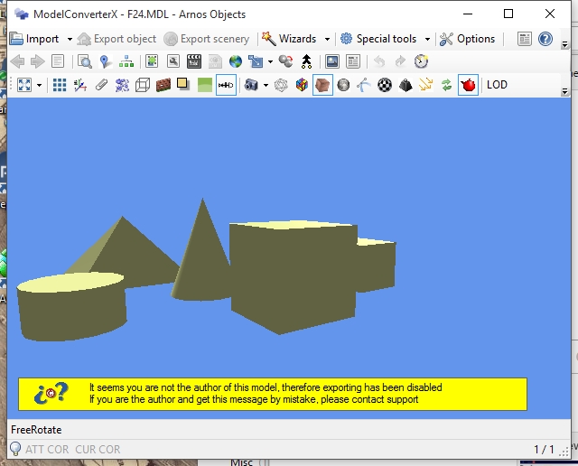
So therefore, together with the release of skin and bone animations, I will introduce some measures in ModelConverterX that will restrict non-genuine use of the tool. As seen in the picture below, when the tool detects that you are not the author of the model it will inhabit export and show a warning. How to detect someone is the author is not easy of course, but the approach that ModelConverterX takes is that it assumes that you are the author if all custom animations and visibility tags are in your ModelDef.xml file. If you don’t have all entries, it is assumed the model is not your work.

I hope that the ani-piracy measures as described above are a good balance between allowing genuine developers to use ModelConverterX in their workflow and making it not too easy for people with bad intentions to steal your hard work. If you have other suggestions or ideas on this balance, please share them with me or the community.
2473 days and counting…
Sometimes a feature is on the wishlist for quite a while. For example the feature request to support skin and bone animations is on the ModelConverterX wishlist for 2473 days already. But since the end of august I’m working on this feature request now and I’m making good progress.
I can already read the skin and bone animations from the MDL files and exporting them again also works. At the moment I’m trying to get the jetway IK animations to export correctly, which is not completely working yet.
Once that is done, there are some minor points that need to be addressed and then this feature will end up in the development release. Let’s see if I can make it before the request is on the wishlist for 2500 days…
Prepar3D v3 support
The development releases of my tools now support Prepar3D v3. In the rest of this post I will provide the details about what this means for the different tools.
ModelConverterX the Convert and Place Object Wizard supports P3D v3 now, so it’s a version you can select to export to. Also the P3D v3 SDK is considered equivalent for the P3D v2 SDK, so when it comes to write MDL and BGL files I see the two versions the same for now. It seems the MDL format still has the same version. If differences are found in the future I might have to add P3D v3 MDL files as a separate output type. But for now either the v3 or v2 SDK is used to export P3D v2/3 MDL files.
scenProc you can provide the path to P3D v3 in the options and select it as a supported version in the combo box, this will ensure that the autogen configuration files are read from the P3D v3 folder. When it comes to exporting BGL files P3D v3 is considered equal to P3D v2 (see the details above for ModelConverterX).
FXEditor together with adding support for P3D v3 I have added a new options form. This allows you to specify the paths of the different FS versions. Using a combo box you can now easily switch between the versions you want to use. The active version determines where effect files are loaded from by default.
Library Creator XML when exporting P3D v2 libraries the P3D v3 SDK can also be used (see details above for ModelConverterX). No other changes made.
I don’t have P3D v3 installed myself yet, so I haven’t been able to test the support properly. If there are any issues, just let me know.
Hierarchy Viewer becomes Hierarchy Editor
The Hierarchy Viewer of ModelConverterX has been renamed to Hierarchy Editor now. As the new name suggests you can now also make changes in this editor.
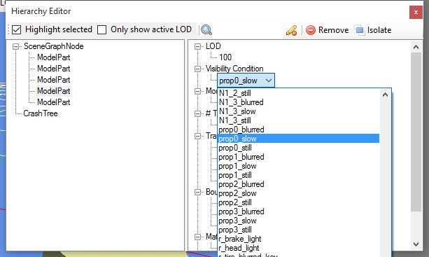
I have added support to change the visibility condition and mouse rectangle of nodes now in this editor. If you click on the name of the currently assigned value, you will get a drop down box where you can select which visibility condition or mouse rectangle you want to use. The content of this drop down box is based on your ModelDef.xml file. If you select the top item named “None” from the list, then the node will have no visiblity condition or mouse rectangle assigned.
So this allows you to add, remove or change those items for each node of your model. Hopefully this is a useful addition and if there are other suggestions on how to improve the hierarchy editor just let me know.

Release candidate
 I have just put a release candidate of the Autogen Configuration Merger tool on the FSDeveloper forum. So if you are interested please test this version as well, hopefully there are no more bugs and a formal release will be there soon.
All details are in the forum post, but basically all I need to finish are the manuals. The last version has an installation mode that will make sure the tool gets properly installed.
Time
 The last year has been very busy, with the moving to a new house, the renovation of that house and the birth of our second child. But even now that things have become a bit more normal again, I still notice that I have much less time than before.
A few weeks ago our oldest child was staying with my parents for a few days, and suddenly we noticed how much easier it was with only one child at home. There was suddenly a lot more time in the evenings to spend on hobbies and other things.
So it’s just a fact that I’m quite short on time for my flightsim hobbies most of the time. In a typical week I can sit down 2 or 3 times behind my FS development PC for maybe an hour or so (that’s the amount of time I would spend on the hobby per evening before). Luckily I can read the forums from my smartphone as well.
So quite often I think fixing this bug or adding this feature shouldn’t be that much work, I’ll have it done in a few days. But when it’s finally done a month has passed again most of the time. So development is going a bit slower than I would want sometimes and there isn’t always the time to work on the ideas I have in my mind.
Let me be clear, I’m not complaining about this situation. Because I do also enjoy the new activities that I now (have to) do in the time I could spend on flightsim before. It’s great fun to spend time with the children and see how they develop. I just wanted to share this with you, so that you understand better why things sometimes go a bit slower. And hopefully when the children are a bit older, there will be more hobby time again…
Windows 10
 I guess nobody has missed that Microsoft released Windows 10 recently. I have upgraded my development laptop as well and things seem to be running fine. Until now I haven’t encountered conversion issues with any of my tools yet, they all seem to be working fine.
ModelConverterX uses OpenGL, so make sure you have the latest Windows 10 driver for your graphics card installed, but that’s the only feedback I got from some users.
So upgrading to Windows 10 seems save, from my tools point of view. I also haven’t had trouble with running FSX (Steam Edition) and the other development tool I often use. But of course I’m not running the tools of a typical flightsimmer, so don’t base your decision to upgrade as well only on my advice 😉
Hierarchy viewer filtering
I have added some extra functionality to the hierarchy viewer of ModelConverterX in the last two days. This feature to allow filtering in all the nodes was on the wishlist for quite a while already and since I needed it to debug an issue I have now finally added it.
The filtering can be done in two ways. First there is the checkbox in the toolbar to only show nodes of the active LOD. When this checkbox is off, all nodes of the model are shown. When it is selected only the nodes of the currently shown LOD in the preview are shown. So if you are looking for issues in a specific LOD this will help to narrow down the amount of nodes to check.
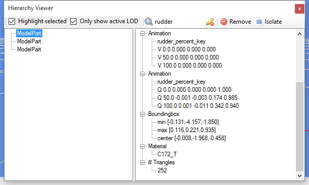
The second way to filter the nodes is even more powerful and that is the search box that you can now also find in the toolbar. If you type any text in this search box only nodes will be shown that match this text. The search is done in material names, animation names, visibility condition names and mouse rectangle names. The picture below shows the default Cessna 172 model where only the rudder parts of the active LOD are shown.

If you clear the search text after you have found the right node, that node will still be selected in the total scenegraph, so that should make it easier to evaluate the parent and child nodes of that specific node.
The isolate button at the toolbar is also new and it will isolate the selected node. What this means is that it will make the selected node the new root node of the model and prune all other nodes. This can be quite destructive so use with care.
Autogen Configuration Merger beta!
 I have just released the first beta version of the new Autogen Configuration Merger tool. I would like to encourage other scenery developers to test this tool and let me know how it works for you. For more details, please see this post on FSDeveloper.
 SceneryDesign.org